
- #7 segment display pin diagram how to
- #7 segment display pin diagram rar
- #7 segment display pin diagram code
#7 segment display pin diagram how to
#7 segment display pin diagram code
Then, send the display code for 0 in port B. In order to display 0, we first need to set the port B as output. Please see the above table to see each segment’s connection to the port pin. This is the connection diagram, Port B is connected to different segments. So if you have 4 digits, you'll need 12 microcontroller pins in total. 7-segment display Interfacing with PIC Microcontroller.
#7 segment display pin diagram rar
Turn a segment on by driving the corresponding segment on (or HIGH for the common cathode variant).įor multiple digits, you'll need 8 microcontroller pins for the segments and the dot plus one extra microcontroller pin for each digit. RAR 7 SEGMENT DISPLAY CIRCUIT DIAGRAM on yx. 74HC4511 DATASHEET PDF,THE APPLICTION NOTES, CIRCUIT DIAGRAM, SCHEMATIC CIRCUITS,VOLTAGE, PIN, PINOUT. Each pin should be connected to a single segment through a resistor,Īnd the common pin should be connected to 5V (or GND if you are using the common cathode variant). Set to "1" to show the colon (clock mode)įor a single digit, you'll need 8 microcontroller GPIO pins. You can set the "common"Īttribute to "cathode" to reverse this behavior.

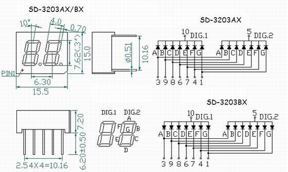
In this circuit, the pins of seven-segment display connect to Arduino pins 2-9. For multi digit displays, use DIG1…DIG4.īy default, the segment pins (A…G, DP, CLN) are connected to the anode (positive side) of the LEDS, and theĬommon pins (COM, DIG1…DIG4) are connected to the cathode (negative side) of the LEDs. The diagram below shows the internal structure of the common cathode. * COM is the common pin for a single digit 7-segment display. Here is the circuit diagram of display decoder which is used to convert a BCD or binary code into a 7 segment code used to operate a 7 segment LED display. Then each Ied or segment cán be easily turnéd ON by appIying logic 0 or low signal through a current limiting resistor to the cathode of any particular led or segment. Seven segment LED display Pin names # Name 7 Segment Display Pin Diagram Series With Each During the practical connections, current limiting resistors are connected in series with each led if needed.


 0 kommentar(er)
